Motion Control Remote Head for Jib Crane
by John Pilgrim
April 8, 2011
The goal of this project is a motorized remote head for use on a jib crane.
The longer term goal is a fully automated rig such as a Milo or Talos or a vehicle mounted Russian Arm.
This project is a follow up to the Camera Slider Dolly I made in 2007 and updated with basic motion control in 2009.
Manual control will be provided by joystick or hand wheels.
Programmable control will be implemented from Houdini, via Python scripting, PySerial, and an Arduino microcontroller, based on Alvin Yap's adaptaion for Houdini of Dan Thompson's Servo Tools for Maya project.
Should the Arduino have insufficient speed to handle the processing requirements, the Make Controller and the Chumby Hacker Board are alternates.
I am currently in the process of drafting and machining the current third
iteration of the design (below and 3D
pdf).
It employes NEMA size 23 stepper motors from Vexta and 24DP (diametric pitch) worms and worm gears from Boston
Gear.
The pan drive is reduced 100:1
and the tilt drive is reduced 72:1, but the stepper housings are designed so
as to allow worm gears of different sizes to be swapped in without any redesign.
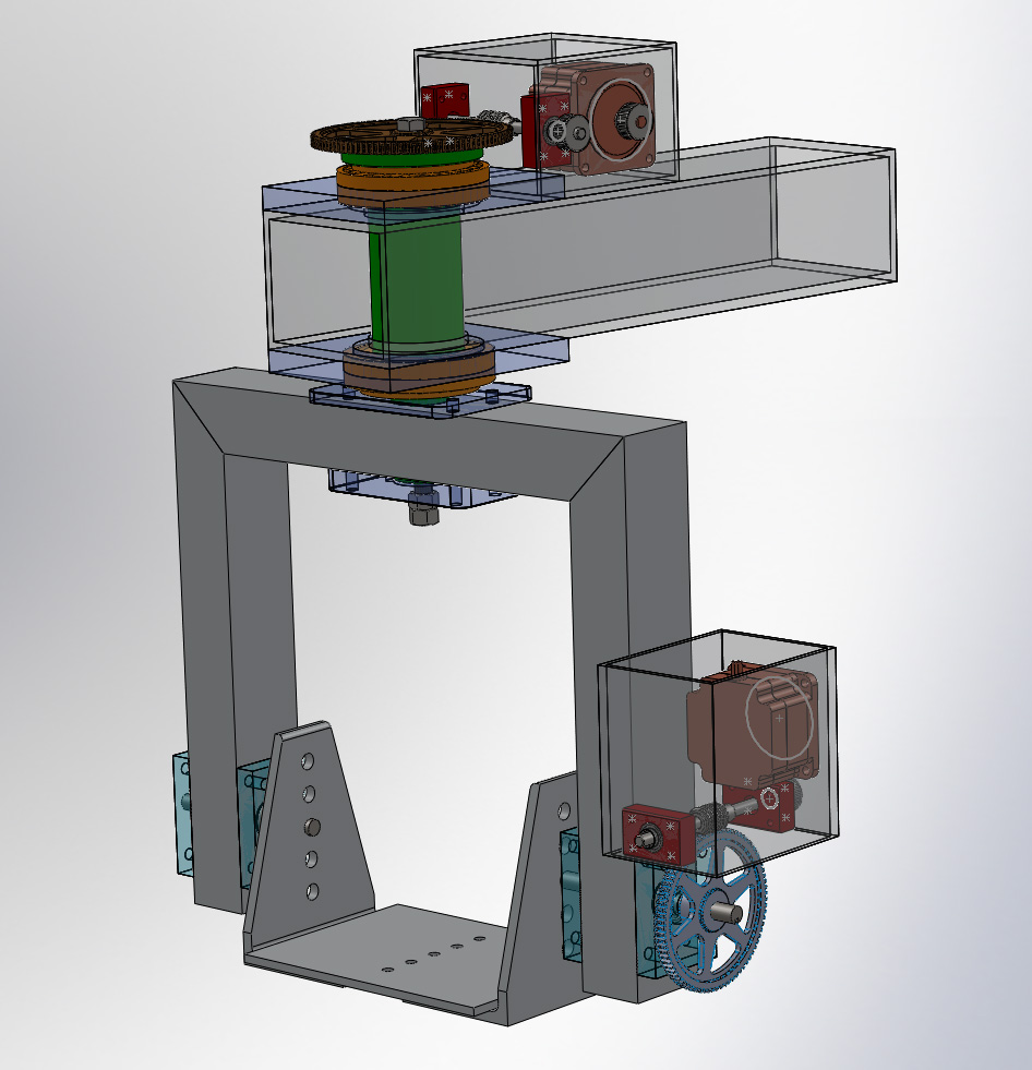
Worm gearing was selected because of the high ratios that can be obtained as well as its inherent resistance to the motor being back driven by the load. The objective is to power down the motor when the camera is not in motion, instead of needing a holding current to maintain position.
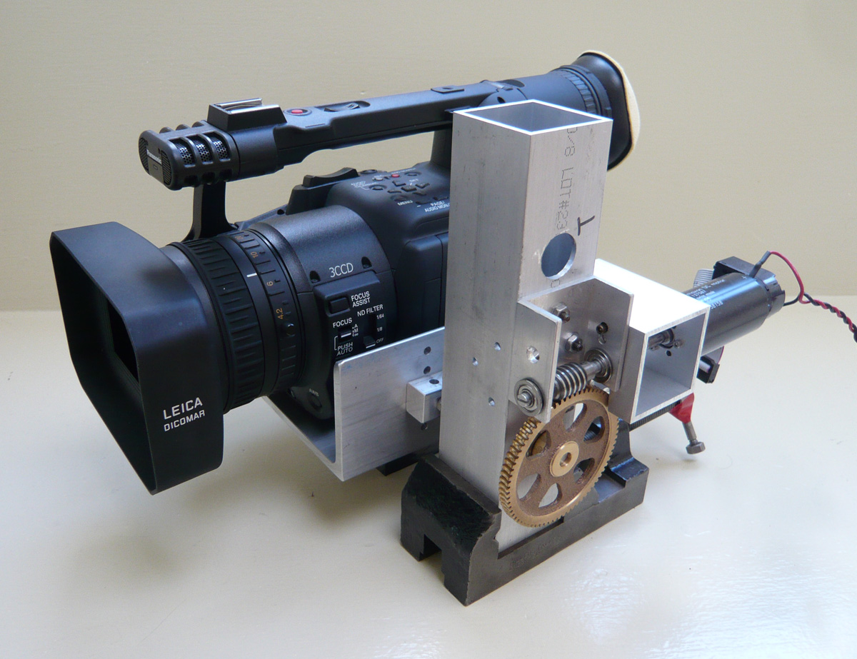
The previous design iteration (below) used the same worm gearing but was driven by a Maxon DC motor (Ø35mm, 90 watt, p/n 138158 consisting of 118800 RE36 + 110514 HEDL). The DC motors had somewhat poor low speed torque and also gave off a lot of noise at low speeds from the PWM. The Motor Mind C by Solutions Cubed was the original motor controller but I short-circuited mine before I could get around to adjusting the PWM frequency to try to abate the noise. I purchased Pololu TReX Jr and Jrk 21v3 controllers as replacements.
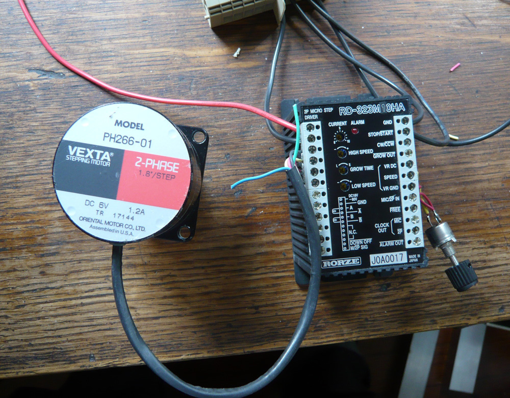
But then I found a number of Rorze RD-323M10HA stepper drivers (specsheet pdf) at one of my favorite local surplus stores.
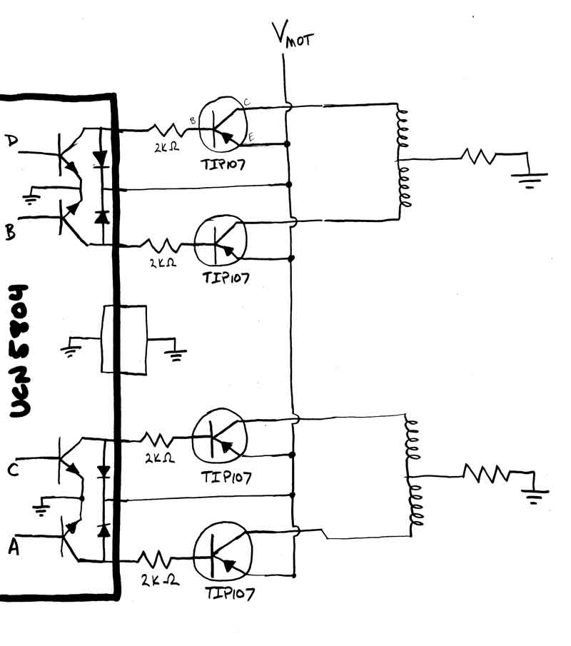
My very first design iteration (below) had also employed stepper motors but involved a hand-built stepper driver based on the Allegro UCN5804 (specsheet pdf). The stepper driver exceeded my ability to design the analog side of the electronics to produce sufficient speed and torque. From this, I had concluded that stepper motors weren't a viable design option.
However, this Rorze driver would spin any stepper I had, from a NEMA size 17 Vexta PX244 to NEMA size 34 Vexta PK296, at a wide range of speeds, with great torque performance. Below is a NEMA 23 Vexta PH266 with an anti-resonance damper on its shaft.
I felt I'd found the holygrail of stepper drivers! The performance was comparable to what I would imagine the well-regarded Gecko drives used in used in DIY CNC conversions should give. The price was much much better than what Gecko drives cost or how much these Rorze drives seem to go for on fleabay, so I went back and bought several more.
This Rorze driver takes a speed and direction input, in contrast to most stepper drivers which take step pulse and direction. The driver also has a "grow time" potentiometer setting to provide trapezoidal accel/decel curve shaping, as well as max "high speed" and min "low speed" potentiometer settings.
The plan is to have Houdini calculate the angular velocity of the camera at each frame, then scale that value to parameter range of the Rorze speed input, and send that to the Arduino to convey to the Rorze driver via an I2C digital potentiometer.
The Arduino will need to conduct a startup routine to measure the current settings of the Rorze and send the speed parameter scale values to Houdini for subsequent operation.
The Rorze driver also outputs a step clock to allow for position encoding. With a TTL or similar counter circuit, the step clock output could be counted and current values returned to Houdini for confirmation of absolute position. I have a number of Agilent HCTL-2020 chips (specsheet pdf) on hand for evaluation as candidates for such a circuit. In my experience, microcontrollers are poor at these counting tasks as they lack the speed to avoid missing pulses.
At some point, a full blown PID feedback mechanism could be implemented, depending on how accurate the non-feedback prototypes are.